new blog
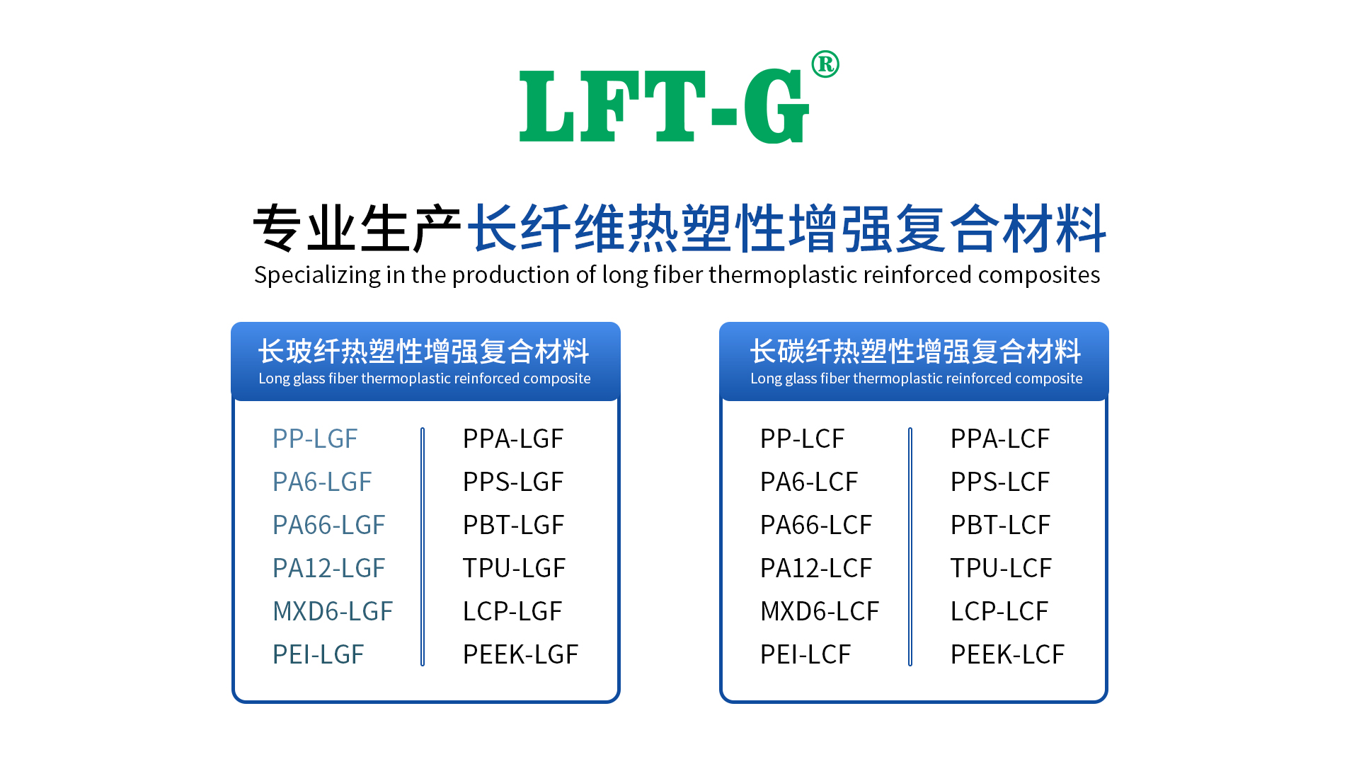
Xiamen LFT Composite Plastic Co.,LTD was established in 2009, is a brand-name global suppliers of long fiber reinforced thermoplastic materials integrating product research & development(R&D), production and sale marketing. Our LFT products have passed the ISO9001&16949 system certification and have obtained lots of national trademarks and patents, covering the fields of automotive, military parts and firearms, aerospace, new energy, medical equipment, power wind energy, sports equipment, etc.

Long fiber reinforced thermoplastics (LFRT) are being used for high mechanical performance injection molding applications. While LFRT technology provides good strength, stiffness and impact properties, the way this material is processed plays an important role in determining what properties can be achieved in the final part.
In order to successfully mold LFRTs, an understanding of some of their unique characteristics is essential. Understanding the differences between LFRTs and conventional reinforced thermoplastics has driven the development of equipment, design and processing techniques to maximize the value and potential of LFRTs.
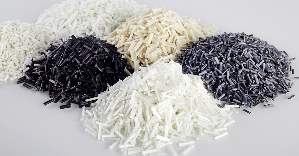
The difference between LFRT and conventional short-cut, short glass fiber reinforced compounds is the length of the fibers. In LFRT, the length of the fibers is the same as the length of the pellets. This is due to the fact that most LFRT is produced through a pultrusion molding process rather than shear blending.
In LFRT manufacturing, continuous tows of untwisted roving of glass fibers are first drawn into a die head for coating and resin impregnation, and after exiting the die head, this continuous strip of reinforcing plastic is either short-cut or pelletized, usually to lengths of 10 to 12 mm. In contrast, conventional short glass fiber composites contain only short cut fibers 3 to 4 mm in length, which are further reduced to typically less than 2 mm in a shear extruder.
Fiber length in LFRT pellets helps to improve the mechanical properties of LFRT - impact resistance or toughness is increased while maintaining stiffness. As long as the fibers maintain their length during the molding process, they form an "internal skeleton" that provides superb mechanical properties. However, a poor molding process can turn a long-fiber product into a short-fiber material. If the length of the fibers is compromised during the molding process, it is not possible to achieve the desired level of performance.
In order to maintain fiber length during the LFRT molding process, there are three important aspects to consider: the injection molding machine, part and mold design, and processing conditions.
I. Equipment Considerations
A frequently asked question about LFRT processing is whether it is possible to mold these materials with our existing injection molding equipment. In most cases, the equipment used to mold staple fiber composites can also be used to mold LFRT, and while typical staple fiber molding equipment is adequate for most LFRT parts and products, some modifications to the equipment can be made to better help maintain fiber length.
A general-purpose screw with a typical "feed-compression-metering" section is well suited for this process, and destructive fiber shear can be reduced by lowering the compression ratio in the metering section. A metering compression ratio of approximately 2:1 is optimal for LFRT products. Manufacturing screws, barrels, and other components from special metal alloys is not necessary because LFRT does not wear as much as conventional short-cut glass fiber reinforced thermoplastics.
Another piece of equipment that might benefit from a design review is the nozzle tip. Some thermoplastic materials are easier to process with a reverse taper nozzle tip that creates a high degree of shear as the material is injected into the mold cavity. However, this nozzle tip can significantly reduce the fiber length of long fiber composites. Therefore, it is recommended to use a slotted nozzle tip/valve assembly with a 100% "free-flow" design, which allows long fibers to easily pass through the nozzle into the part.
In addition, nozzles and gate holes should have a generous diameter of 5.5mm (0.250in) or more and no sharp edges. It is important to understand how the material flows through the injection molding equipment and to determine where shear will break up the fibers.
II. Component and Mold Design
Good part and mold design also goes a long way toward maintaining the fiber length of LFRT. Eliminating sharp corners around part edges, including rib lines, tabs, and other features, avoids unnecessary stresses in the molded part and reduces fiber wear.
Parts should be of a nominal wall design with uniform and consistent wall thickness. Large variations in wall thickness can result in inconsistent filling and unwanted fiber orientation in the part. Where parts must be thicker or thinner, avoid sudden changes in wall thickness to avoid the formation of high shear areas that can damage fibers and be a source of stress concentrations. Usually try to open the gate in the thicker wall and flow into the thinner part, keeping the end of the fill in the thinner part.
Generic good plastic design principles suggest that keeping the wall thickness below 4mm (0.160in) will promote good uniform flow and reduce the likelihood of dents and voids. For LFRT composites, the optimum wall thickness is usually around 3mm (0.120in), with a minimum thickness of 2mm (0.080in). With wall thicknesses less than 2mm, the material has an increased probability of its fibers breaking as it enters the mold.
The part is only one aspect of the design; it is also important to consider how the material enters the mold. When runners and gates guide material into the cavity, a significant amount of fiber breakage can occur in these areas without proper design.
When designing a mold for molding LFRT composites, a fully rounded runner with a minimum diameter of 5.5mm (0.250in) is optimal. Any form of runner other than a fully rounded runner will have sharp corners, and they can damage the fiberglass reinforcement by adding stress during the molding process. Hot runner systems with open gates are acceptable.
The gate should have a minimum thickness of 2mm (0.080in). If possible, locate the gate along an edge that does not impede the flow of material into the cavity. Gates on the surface of the part will need to be turned 90° to prevent the initiation of fiber breaks that would degrade the mechanical properties.
Finally, it is important to pay attention to the position of the fusion lines and to know how they affect the areas that will be subjected to loads (or stresses) when the part is used. Fusion lines should be moved to areas where stress levels are expected to be lower through proper gate layout.
Computerized mold filling analysis can help determine where these fusion lines will be positioned. Structural Finite Element Analysis (FEA) can be used to compare the locations of high stresses with the locations of the fusion lines identified in the mold filling analysis.
It should be noted that these part and mold designs are only recommendations. There are many examples of parts with thin walls, wall thickness variations, and delicate or fine features that utilize LFRT complexes to achieve good performance. However, the farther one deviates from these recommendations, the more time and effort it will take to ensure that the full benefits of LFRT are realized.
III. Processing conditions
Processing conditions are critical to the success of LFRT. With the right processing conditions, it is possible to prepare good LFRT parts using a universal injection molding machine and a properly designed mold. In other words, even with proper equipment and mold design, fiber length may be compromised if poor processing conditions are used. This requires an understanding of what the fibers will encounter during the molding process and identifying areas that will cause excessive fiber shear.
First, monitor the back pressure. High backpressure introduces large shear forces into the material that will reduce fiber length. Considering starting with zero backpressure and only increasing it to the point where the screw returns uniformly during feeding, a backpressure of 1.5 to 2.5 bar (20 to 50 psi) is usually sufficient to obtain a consistent feed.
High screw speeds also have a detrimental effect. The faster the screw rotates, the more likely solids and unmelted material will enter the compression section of the screw causing fiber damage. Similar to the recommendations for back pressure, the speed should be kept as low as possible to the minimum level required to stabilize a filled screw. Screw speeds of 30 to 70 r/min are common when molding LFRT composites.
During injection molding, melting occurs through two factors that act together: shear and heat. Because the goal is to preserve the length of the fibers in LFRT by reducing shear, more heat will be required. Depending on the resin system, the temperature at which LFRT compounds are processed will typically be 10 to 30°C higher than conventional molded compounds.
However, before simply increasing the barrel temperature across the board, be aware of the inverse barrel temperature distribution. Typically, barrel temperatures rise as material moves from the hopper to the nozzle; however, for LFRT, higher temperatures are recommended at the hopper. Inverting the temperature distribution causes the LFRT pellet to soften and melt before it enters the compression section of the high-shear screw, thus facilitating fiber length retention.
A final note on processing relates to the utilization of reused material. Grinding molded parts or sprues typically results in lower fiber lengths, so the addition of reuse material can affect the overall fiber length. In order not to significantly degrade mechanical properties, the recommended maximum amount of reclaimed material is 5%. Higher amounts of reclaim can negatively affect mechanical properties such as impact strength.
follow us :


-- get updates with latest topics

 e-mail
 English
 français
 Deutsch
 русский
 italiano
 español
 português
 العربية
 日本語
日本語 한국의
한국의 中文
中文