new blog

In the injection molding process of glass fiber-reinforced materials, fiber floating is one of the most common surface defects. It appears as an uneven surface caused by exposed glass fibers on the part. This issue not only affects the visual appearance of the product but can also negatively impact secondary processes such as painting, coating, or electroplating. Today, we will take a deep dive into the root causes of fiber floating and explore effective solutions.
2. In-Depth Analysis of Injection Molding Process Factors
Slow Filling Speed: The "Invisible Driver" Behind Fiber Floatation
Core Issue: Slow filling allows glass fibers to migrate to the surface of the molded part.
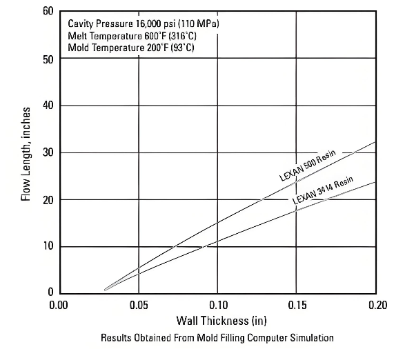
Low Melt Temperature: The "Temperature Threshold" for Material Flow
Key Finding: For every 10 °C decrease in melt temperature, surface fiber floatation increases by 15–20%.
Professional Recommendation:
Use a melt probe to measure the actual melt temperature instead of relying solely on barrel setpoints.
Increase melt temperature to the upper limit of the recommended range (while avoiding material degradation).
Pay attention to back pressure settings to prevent excessive fiber breakage.
Practical Tips:
Use a high-temperature mold temperature controller (>100 °C) or thermal oil system.
Clearly indicate the required type of mold temperature controller to avoid misuse.
Extra care is needed for safety when operating at high temperatures.
3. Key Considerations in Mold Design
Venting System: The Balance Between Speed and Quality
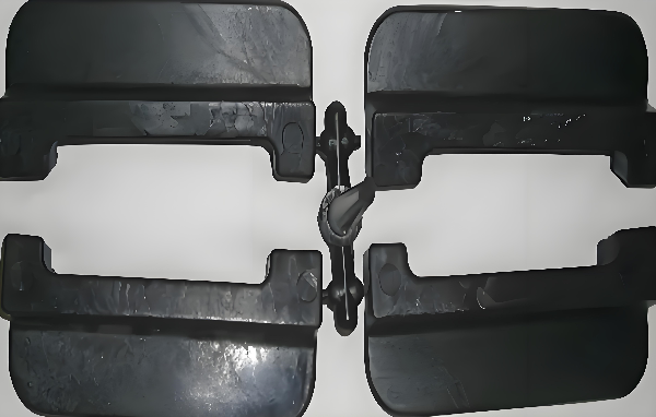
Core Conflict: Fast filling requires sufficient venting, but excessive venting may lead to flash and fiber floatation defects (e.g., weld lines, trapped air).
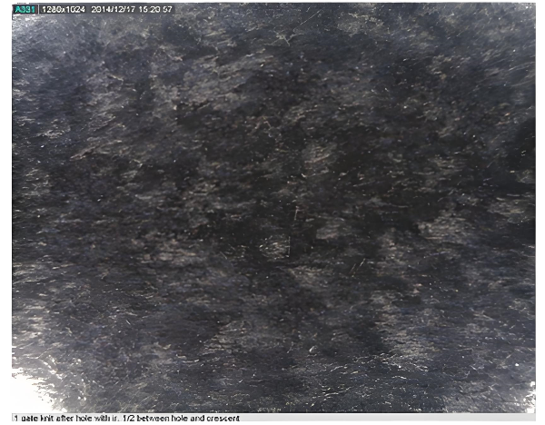
Fiber Floatation Defect Image (with weld lines and trapped air)
Hot Runner Temperature: The Often Overlooked "Thermal Blind Spot"
Common Misconception: The hot runner temperature is set inconsistently with the barrel temperature.
Best Practice:
Set the hot runner temperature within the material's recommended melt temperature range.
Use thermocouples for precise temperature control.
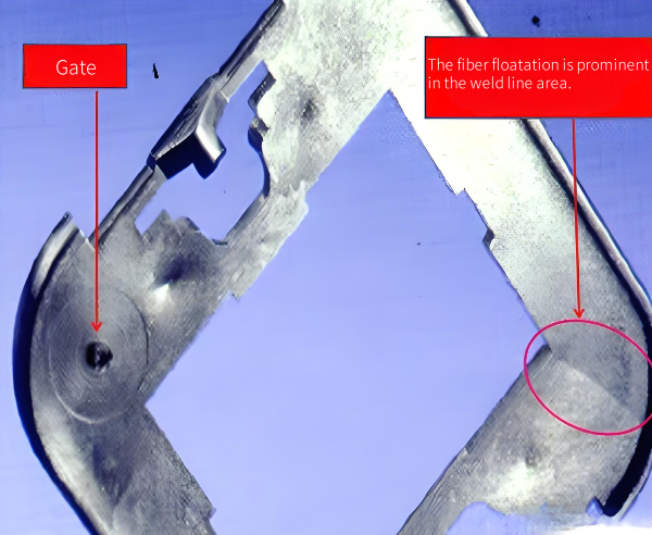
Gate Design: The First Barrier to Flow
Design Guideline:
Avoid excessive restriction at the gate that can cause a sudden pressure spike.
Gate size and location should match the flow characteristics of the material.
Prevent excessively small gates to avoid jetting marks and aggravated fiber floatation.
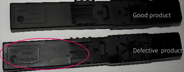
Defective Part Image: Jetting-Induced Fiber Floatation
Summary: Solutions to Fiber Floatation Issues
Priority Principle: Address the primary cause first (typically process parameters), then tackle secondary factors.
Systematic Thinking: Develop an integrated solution covering process–mold–equipment–material.
Prevention-Oriented: Consider fiber floatation countermeasures during the early stages of new mold development.
Data-Driven Approach: Establish process control charts for key parameters.
Continuous Improvement: Build a quick-response mechanism and knowledge database for fiber floatation issues.
follow us :


-- get updates with latest topics

 e-mail
 English
 français
 Deutsch
 русский
 italiano
 español
 português
 العربية
 日本語
日本語 한국의
한국의 中文
中文